
EOTPR is a well-established non-destructive fault isolation tool for advanced IC devices. These examples will show how EOTPR has been implemented to investigate a wide range of advanced package types, including 2.5D and 3D packages, wafer level fanout packages, and microelectromechanical (MEMs) devices. Further, we present the recent improvements to the EOTPR instrument and the results from a novel modelling approach that has the potential of vastly speeding up the fault localisation analysis.
Electro-Optical Terahertz Pulse Reflectometry (EOTPR) is an implementation of the time domain reflectometry (TDR) technique at terahertz frequencies, proven to enhance fault isolation accuracy to better than 10 µm. As in conventional TDR, the fault detection accuracy of EOTPR is a function of the rise time of the incident pulse, the time-based jitter, and signal-to-noise ratio (SNR). The EOTPR instrument generates a terahertz pulse using an ultrafast laser and a pair of photoconductive switches for signal generation and detection, resulting in a system with (i) high measurement bandwidth, (ii) low time-base jitter, and (iii) a high time-base resolution.
Compared to conventional TDR, EOTPR generates signals with faster rise time, has greater SNR, and a much-reduced time base jitter; system properties that offer the potential for a significantly increased distance-to-defect accuracy.A schematic diagram of the EOTPR system is shown below.
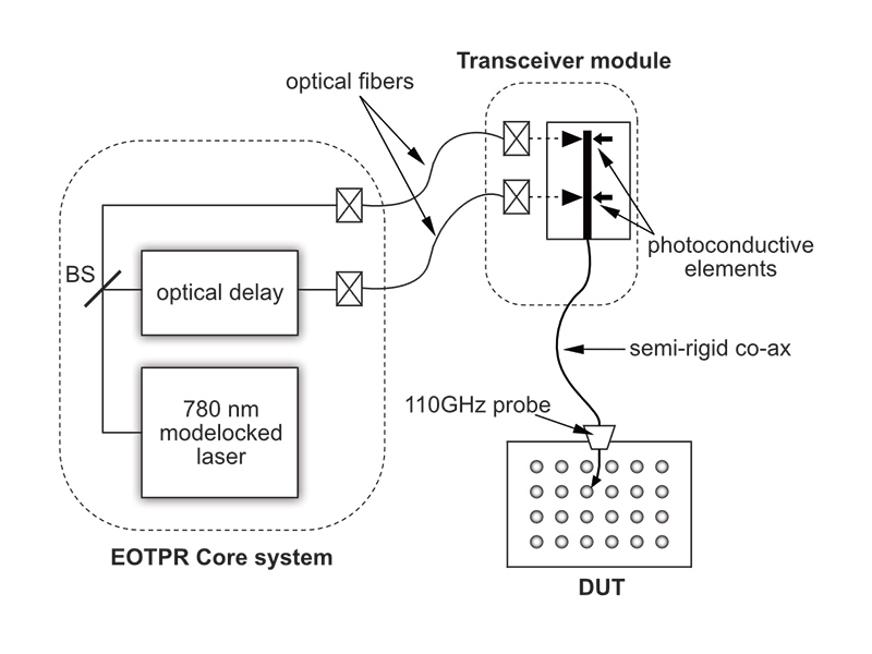
During operation, pulses are launched into a device-under-test (DUT) via a high frequency circuit probe. Portions of the pulse are reflected as it encounters changes in impedance, such as dead opens, resistive opens, and short circuit defects, within the IC. These reflections are measured by the detector photoconductive switch and are recorded as a function of time, resulting in the EOTPR waveform. An example waveform for an open high frequency probe is shown below.
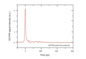
As EOTPR utilises an impulse response rather than the step response of conventional TDR, high and low impedance discontinuities in a DUT result in positive peaks and negative troughs, respectively, in the measured waveform. The magnitude of these features indicates the size of the impedance change encountered by the pulse and their arrival time gives the location of the fault. EOTPR is, by necessity, a comparative technique; to understand whether a waveform feature arises from a fault in the DUT, it is essential to compare the waveform from a known good device (KGD).
To localise a fault within the DUT the time-domain waveform can be readily converted into the distance-domain. This can be accurately achieved by measuring reference devices that have impedance features, such as opens, at known locations. The effective dielectric constant of the DUT can be determined by measuring the time required for the EOTPR signal to travel between reference features or known locations, which is then used to convert the EOTPR waveform from time to distance.
EOTPR is now a well-established technique in failure analysis workflows and has been used to interrogate a wide range of different device architectures. Examples below show how EOTPR can be used to accurately localise faults in advanced IC packages.
For more information see https://teraview.com/eotpr/
No comments:
Post a Comment